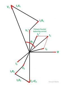
Vector diagram of transformer at vectorified com
Table of Contents
Table of Contents
If you want to understand the behavior of an electrical system, you need to understand phasor diagrams. But, many people get intimidated by thinking about how to draw a phasor diagram for a transformer, and that’s where we come in. Phasors diagrams are vital for understanding how electrical circuits work, and they are easy to create once you get the hang of it.
For those who are new to the world of electricity, drawing a phasor diagram can be challenging. You might not know where to start or what tools to use. Even those who have worked with phasor diagrams before might find themselves feeling uneasy when working with transformers. This uncertainty is due to the complexity of the system and the need to get things exactly right.
When learning how to draw a phasor diagram for a transformer, the first step is to understand the basics. A phasor diagram is a graphical representation of the electrical current and voltage in a circuit. It is used to show the magnitude and the phase angle of the voltage or current vectors. In a transformer, it is used to illustrate the relationship between the primary and secondary voltage and current.
To draw the phasor diagram of a transformer, you must first identify the winding connections and the phase relationships between the primary and secondary windings. From this information, you can construct the phasor diagram to show the voltage and current relationships between the two windings.
My Journey: Learning How to Draw a Phasor Diagram for a Transformer
When I first started learning how to draw a phasor diagram for a transformer, I was intimidated by the complex nature of the task. However, I was determined to learn this essential skill as I knew it would be of great benefit in the long run. I started by watching online tutorials, which walked me through the process step-by-step. Additionally, I read articles and textbooks to gain a deeper understanding of phasor diagrams.
After a lot of practice and repetition, I finally got the hang of it. Creating phasor diagrams became second nature, and I found myself able to understand electrical systems much better. It allowed me to visualize how the current was flowing, which made it easier to troubleshoot any problems that arose.
Understanding the Importance of Phasor Diagrams for Transformers
Phasor diagrams play a critical role in the analysis of electrical systems, especially in transformers. They help us understand the relationship between voltage and current in a complex electrical system. By constructing a phasor diagram for a transformer, you can gain insight into how a transformer will act under different loads, and help you optimize the system for maximum efficiency.
Constructing the Phasor Diagram for a Transformer
The phasor diagram for a transformer consists of two main parts: the primary winding and the secondary winding. The primary winding is represented by a vertical line, and the secondary winding is represented by a horizontal line. Voltage and current relationships are then represented by arrows on the phasor diagram. The length of the arrows represents the magnitude of the voltage or current, while the angle represents the phase relationship between the two.
Step-by-Step Guide to Drawing a Phasor Diagram for a Transformer
1. Identify the connections of the primary and secondary windings.
2. Establish the phase angles between the primary and secondary voltages.
3. Sketch the primary voltage phasor as a reference vector along the vertical axis.
4. Draw the secondary voltage phasor perpendicular to the primary voltage phasor along the horizontal axis.
5. Draw the primary current phasor parallel to the primary voltage phasor.
6. Determine the turn’s ratio and sketch the secondary current phasor, which is parallel to the secondary voltage phasor.
Demonstrating the Importance of Phasor Diagrams for Transformers
One of the significant benefits of phasor diagrams is their usefulness in analyzing system performance. Modern power systems operate at high voltage, which makes visualizing the system more challenging. However, phasor diagrams provide an efficient means of visualizing how the system is operating, which can help diagnose problems such as overloading or equipment failure, allowing users to troubleshoot the problem and fix it in a timely manner.
Question and Answer
Q. Why is it essential to draw a phasor diagram for a transformer?
A. A phasor diagram is used to visualize the voltage and current relationships between the primary and secondary windings in a transformer. It is essential to understand this relationship to optimize the system for maximum efficiency.
Q. Are phasor diagrams difficult to draw?
A. Drawing phasor diagrams may seem challenging at first, but with practice, it becomes much easier. Additionally, several online tutorials and textbooks can help you learn how to draw phasor diagrams.
Q. Can phasor diagrams help diagnose power problems in a system?
A. Yes, phasor diagrams provide an efficient means of visualizing power system performance, allowing you to diagnose problems such as overloading or equipment failure.
Q. How can phasor diagrams help optimize a system for maximum efficiency?
A. By visualizing the voltage and current relationships between the primary and secondary windings of a transformer, you can optimize the system for maximum efficiency by adjusting the load or the number of turns in the windings.
Conclusion of How to Draw a Phasor Diagram for a Transformer
As you can see, drawing a phasor diagram for a transformer is critical to understanding the operation of an electrical system. While it may seem daunting at first, with some practice and repetition, creating these phasor diagrams will become natural. By understanding the importance of phasor diagrams and the steps involved in creating them, you can diagnose problems in your power system and optimize it for maximum efficiency.
Gallery
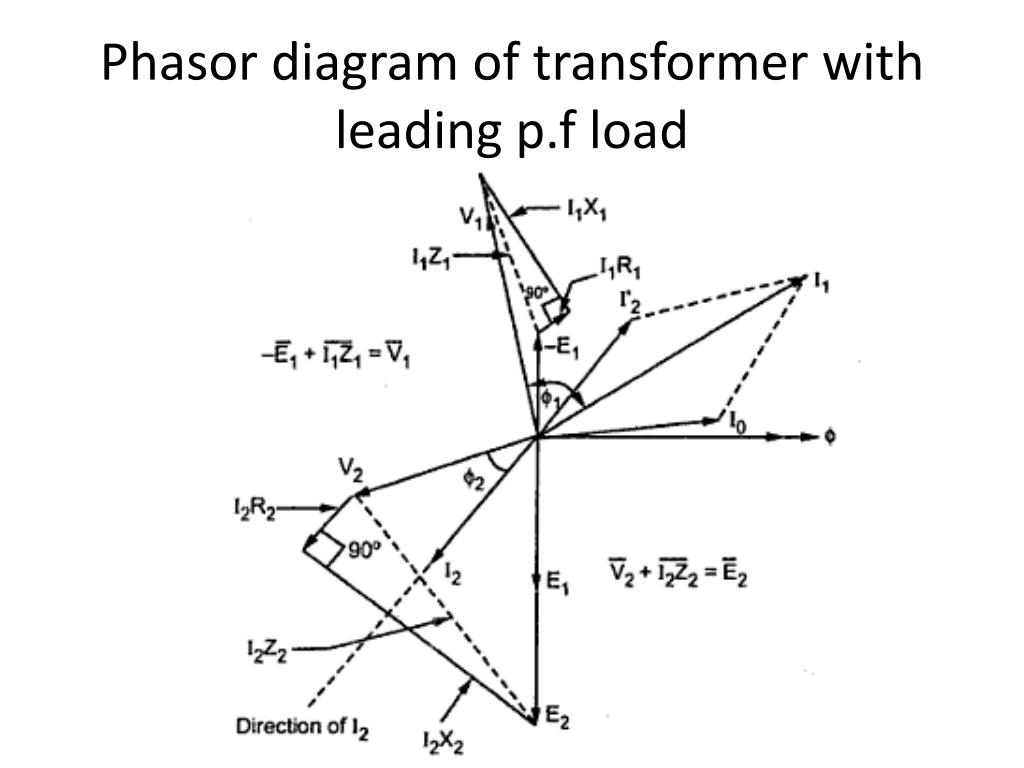
PPT - Transformers PowerPoint Presentation, Free Download - ID:4523502

Photo Credit by: bing.com / transformer load phasor diagram leading transformers ppt powerpoint presentation circuit
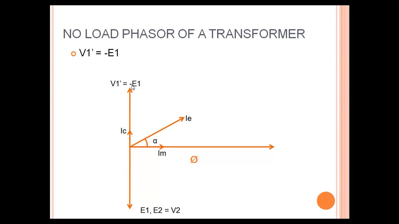
Transformer Loading And On-load Phasor Diagrams

Photo Credit by: bing.com / phasor test
Vector Diagram Of Transformer At Vectorified.com | Collection Of Vector

Photo Credit by: bing.com / diagram transformer vector phasor load condition vectorified
AC MACHINES-1 (66761) Theory: Draw The Vector Diagram Of A Transformer

Photo Credit by: bing.com /
Transformer ON Load Condition - Phasor Diagram On Various Load

Photo Credit by: bing.com / phasor transformer inductive


